|
| |
|
| |
E-1, E1 Repeater, E-Extender | 
|
General
Wire
Indicators
Connectors
Physical/Electrical
Note: This product is NOT intended for 10BaseT or Ethernet. E1 modulation is designed for use with twisted pair solid wire phone cables. The E-extender does NOT extend ethernet connections... only E1 connections.
Each pair of E-1 Extenders may be located up to 4000 feet apart. The Extender circuitry is rated to -43 dB dynamic range at the E-1 rate of 2.048 Mbps. As implemented, the parts are slightly de-rated to provide long life at extended temperature range. Therefore the distances specified in this document are only 4000 feet. Solid copper 22 or 24 AWG, two twisted pair is the preferred cable for connection between the Extenders. Connection to the Extender is made through RJ-45 modular connectors or 4-wire screw down barrier strips. Each Extender comes standard with two screw down barrier strips and one RJ-45 connector. If only RJ-45 connections are desired, extra RJ-45 adapters (part number 9502122) may be ordered.
The 120/240 VAC E-Extenders are powered by a small wall-mount transformer. The Extenders are designed for connections between E-1 equipment such as PBXs, E-1 multiplexers, E-1 line drivers, CSUs, routers or any other E-1 equipment requiring long customer owned cable runs. E-Extenders may be used to connect this equipment across a campus, between floors of a high-rise office building or between office buildings with underground cable runs. The E-Extenders are transparent to the type of data sent over the E-1 link. The data can be D-4 format, ESF, PRI, G.703, G.704, etc.
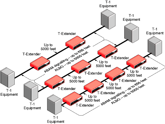
The Extenders are most often used in pairs to extend a telephone company demarc. For example, if a CSU or DSU is limited to 655 feet and is connecting to a phone company smart jack demarc which is limited to 655 feet, the E-Extenders are used in pairs to extend that distance up to 5000 feet.
E-1 repeater
Extends E-1 bi-polar signal
Up to 4000 feet between E-Extenders
Two twisted pair solid copper 22 or 24 AWG
Other types will affect operational distance
Front panel power LED
RJ-45 modular 8-conductor connectors
Pin 1 = Receive
Pin 2 = Receive
Pin 4 = Transmit
Pin 5 = Transmit
4-Wire barrier strip
Pin 1 = Receive
Pin 2 = Receive
Pin 3 = Transmit
Pin 4 = Transmit
Connect the transmit pair of one Extender to the receive pair of the other Extender. Pairs are not polarity sensitive
Units supplied with 2 screw down connectors, 1 RJ-45 connector
A cable cross-over is required between two Extenders if using straight RJ-45 cables. This cable connects the receive pair to one Extender to the transmit pair of the other Extender.

| Data Comm for
Business Inc. 2949 County Road 1000 E Dewey, Il 61840 |
Voice:
217-897-6600 Toll Free: 800-4-DCB-NET Toll Free: 800-432-2638 |
Email: Contact Page Web: www.dcbnet.com Fax: 217-897-8023 |
|
| All DCB web pages copyright ©1995- Data Comm for
Business, All rights reserved. EtherPath®, EtherSeries®, EtherPoll®, EtherBridge® and EtherModem® are Registered Trademarks of Data Comm for Business, Inc. |
|||