|
| |
|
| |


|
|
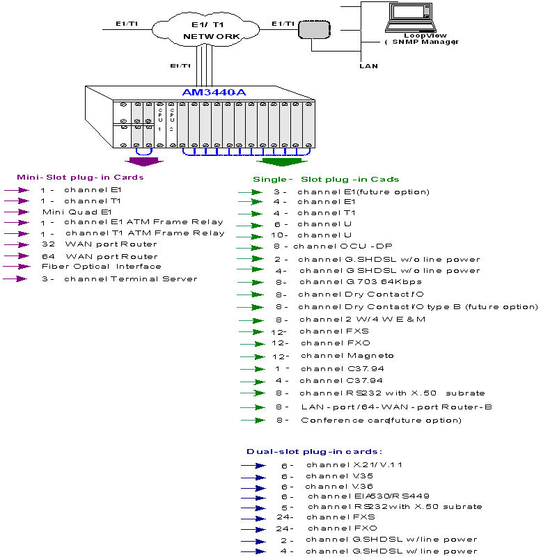
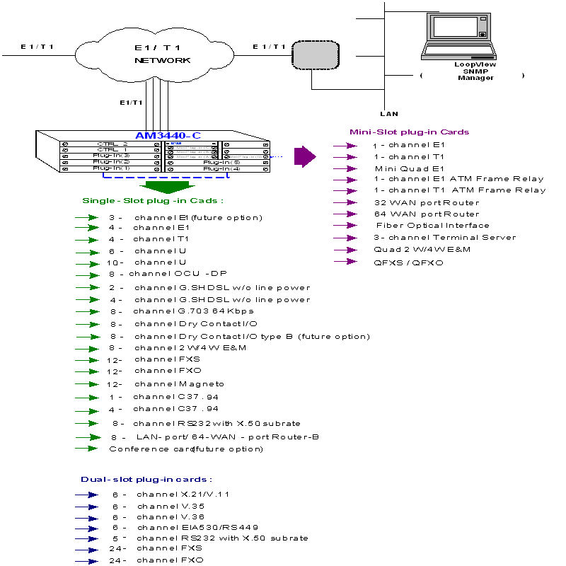
The AM3440-A/B/C is an access DCS-MUX that can combine various digital access interfaces into E1 or T1 lines for convenient transport and switching. The AM3440 Access DCS-MUX provides access for a variety of interfaces, including mini Quad E1, Quad E1/T1, ATM/FR, 32 WAN port Router, 64 WAN port Router-A, Router-B, FOM, Terminal Server Card, G.SHDSL, G.703, U type, X.21, V.35, V36, EIA530/RS449, RS232, 8RS232, QEM, QFXO, QFXS, 8EM, 12FXS, 12FXO, 24FXS, 24FXO, and Magneto. These interfaces are compatible with other Loop products such as the Loop-H 3900 (MDSL), LoopH3300 and the Loop-U3500 (U). Using these products, a DTE interface can be extended over copper wire pairs. For as many Quad E1/T1 plug-in cards, each card can have as many as 124/96 time slots for the G.SHDSL, U, RS232, X.21, V.35, V.36 and EIA530/RS449 interfaces are then multiplexed to fill 4 E1/T1 line, with full flexibility of time slot interchange for all incoming lines. AM3440 also supports fiber optical plug-in module, which can be used to aggregate up to 4 E1 channels to single fiber optical interface to connect with other AM3440 or O9310.
AM3440-A has capacity for 12 single slots and 4 mini plug-in slots. AM3440-B has capacity for 3 single slots and 4 mini plug-in slots. AM3440-C has capacity for 5 single slots and 4 mini plug-in slots. All interface cards and controller cards can be used in AM3440-A/B/C, except for the G.SHDSL line power card, which is for the AM3440-A only and mini-slot QEM/QFXS/QFXO interface cards, which are for the AM3440-B and AM3440-C only.
This unit is a full cross-connect and can act as a mini DACS. This means that one or more of the WAN ports can be used as a Drop & Insert function with fractional E1/T1 lines, which can be muxed into a full E1/T1 line.
Redundancy is available in dual CPU controller and power supply options, making it an excellent fit for critical applications. Although the chassis does not contain and has no need for fan cooling, an external fan tray is available.
The AM3440 supports local control and diagnostics by using an external 2-line by 40-character LCD display and keypads, or by using a VT-100 terminal connected to the console port. The AM3440 also supports Ethernet, SLIP, Telnet, and SNMP, so that it can be controlled and diagnosed from remote locations as well. An in-band management channel with GUI is available. In addition to the LCD display, there are LED indications for all plug-in cards.
|
|
Plug-in cards |
AM3440-A |
AM3440-B |
AM3440-C |
|
Mini-Slot |
1-channel E1 |
√ |
√ |
√ |
|
1-channel T1 |
√ |
√ |
√ |
|
|
Mini Quad E1 |
√ |
√ |
√ |
|
|
1-channel E1 ATM/Frame Relay |
√ |
√ |
√ |
|
|
1-channel T1 ATM/Frame Relay |
√ |
√ |
√ |
|
|
32 WAN port Router |
√ |
√ |
√ |
|
|
64 WAN port Router-A |
√ |
√ |
√ |
|
|
Fiber optical interface |
√ |
√ |
√ |
|
|
√ |
√ |
√ |
||
|
Quad 2W/4W E&M |
x |
√ |
√ |
|
|
x |
√ |
√ |
||
|
Single-Slot |
3-channel E1 (future option) |
√ |
√ |
√ |
|
TDM Over Ethernet |
√ |
√ |
√ |
|
|
4-channel E1 |
√ |
√ |
√ |
|
|
4-channel T1 |
√ |
√ |
√ |
|
|
6-channel U |
√ |
√ |
√ |
|
|
10-channel U |
√ |
√ |
√ |
|
|
8-channel OCU-DP |
√ |
√ |
√ |
|
|
2-channel G.SHDSL (2 pairs) w/o line power |
√ |
√ |
√ |
|
|
4-channel G.SHDSL (1 pair) w/o line power |
√ |
√ |
√ |
|
|
8-channel G.703 card at 64 Kbps data rate |
√ |
√ |
√ |
|
|
8-channel Dry Contact I/O |
√ |
√ |
√ |
|
|
8-channel Dry Contact I/O type B (future option) |
√ |
√ |
√ |
|
|
8-channel 2W/4W E&M |
√ |
√ |
√ |
|
|
12-channel FXS |
√ |
√ |
√ |
|
|
12-channel FXO |
√ |
√ |
√ |
|
|
12-channel Magneto |
√ |
√ |
√ |
|
|
1-channel low speed optical (C37.94) |
√ |
√ |
√ |
|
|
4-channel low speed optical (C37.94) |
√ |
√ |
√ |
|
|
8-channel RS232 with X.50 subrate |
√ |
√ |
√ |
|
|
8-LAN-port/ 64-WAN-port Router-B |
√ |
√ |
√ |
|
|
Conference card (future option) |
√ |
√ |
√ |
|
|
Dual-Slot |
6-channel X.21/V.11 |
√ |
√ |
√ |
|
6-channel V.35 |
√ |
√ |
√ |
|
|
6-channel V.36 |
√ |
√ |
√ |
|
|
6-channel EIA530/RS449 card |
√ |
√ |
√ |
|
|
5-channel RS232 with X.50 subrate |
√ |
√ |
√ |
|
|
24-channel FXS |
√ |
√ |
√ |
|
|
24-channel FXO |
√ |
√ |
√ |
|
|
2-channel G. SHDSL (2 pairs) with line power |
√ |
x |
x |
|
|
4-channel G. SHDSL (1 pair) with line power |
√ |
x |
x |
LOOP-AM3440 Access DCS-MUX Product Specifications
Network Line Interface - T1
|
Line Rate |
1.544 Mbps 50 bps |
Output Signal |
DSX1 |
|
Line Code |
AMI or B8ZS |
Framing |
D4/ESF (selectable) |
|
Input Signal |
ABAM cable length up to 655 feet |
Connector |
RJ48C |
Network Line Interface - E1
|
Line Rate |
2.048 Mbps 50 ppm |
Framing |
ITU G.704 |
|
Line Code |
AMI or HDB3 |
Connector |
BNC/RJ48C |
|
Input Signal |
ITU G.703 to -10dB |
Electrical |
75 ohm Coax/120 ohm twisted pair |
|
Output Signal |
ITU G.703 |
Jitter |
ITU G.823 |
Network Line Interface - Mini 4E1
|
Line Rate |
2.048 Mbps 50 ppm |
Framing |
ITU G.704 |
|
Line Code |
AMI or HDB3 |
Connector |
DB25S |
|
Input Signal |
ITU G.703 to -10dB |
Electrical |
75 ohm Coax/120 ohm twisted pair |
|
Output Signal |
ITU G.703 |
Jitter |
ITU G.823 |
Network Line Interface - 4T1
|
Line Rate |
1.544 Mbps 50 bps |
Output Signal |
DSX1 |
|
Line Code |
AMI or B8ZS |
Framing |
D4/ESF (selectable) |
|
Input Signal |
ABAM cable length up to 655 feet |
Connector |
RJ48C |
Network Line Interface - 3E1
|
Line Rate |
2.048 Mbps 50 ppm |
Framing |
ITU G.704 |
|
Line Code |
AMI or HDB3 |
Connector |
BNC/RJ48C |
|
Input Signal |
ITU G.703 to -10dB |
Electrical |
75 ohm Coax/120 ohm twisted pair |
|
Output Signal |
ITU G.703 |
Jitter |
ITU G.823 |
Network Line Interface - 4E1
|
Line Rate |
2.048 Mbps 50 ppm |
Framing |
ITU G.704 |
|
Line Code |
AMI or HDB3 |
Connector |
BNC/RJ48C |
|
Input Signal |
ITU G.703 to -10dB |
Electrical |
75 ohm Coax/120 ohm twisted pair |
|
Output Signal |
ITU G.703 |
Jitter |
ITU G.823 |
ATM Frame Relay Network Line Interface
|
Supporting Network Interworking (FRF.5) and service interworking (FRF.8). |
||
|
Network Interface: |
||
|
T1 ATM UNI |
|
|
|
FR (n x 64 Kbps, n=1 to 31) |
|
|
E1 ATM UNI |
|
|
|
FR (n x 64 Kbps, n= 1 to 31) |
|
|
Up to 31 logical FR channels can be concentrated/ de-concentrated to FR or ATM. |
||
|
Service Ports: |
||
|
n x 64 Kbps, n=1 to 24 |
|
|
n x 64 Kbps, n= 1 to 31 |
|
|
Supports HDLC to FR |
||
|
Supports HDLC to ATM |
||
|
Supporting FR to FR multiplexing. |
||
|
Supports up to 128 DLCIs for total of 31 FR interfaces. |
||
|
Supports up to 128 VCs. |
||
|
Peak cell rate on DLCI basis. |
||
|
Manufacturing disable/enable ATM scrambling for internal testing (E1 ATM only). |
||
|
AAL0 and AAL5 are supported in the ATM adaptation layer. |
||
|
Supports VBR service. |
||
|
ITU FR management protocols are supported. |
||
|
Flash memory software download through RS485. |
||
|
Only the PVC type of ATM/FR service is supported. |
||
Router Interface
|
Number of ports |
2 LAN ports, Max. 32 WAN ports |
|
Physical Interface |
10 BaseT x 1, 10/100 BaseT x 1 |
|
Connector |
RJ45 |
|
Routing protocol |
RIP-I, RIP-II |
|
Data Rates |
Channelized N x 64 Kbps up to T1/E1 capacity |
|
Supporting Protocols |
TCP/IP, PPP, HDLC |
|
Management |
VT-100, SNMP |
TDM Over Ethernet Interface
Download Detailed Data Sheet
|
Number of ports |
Four Ethernet Ports for WAN or LAN port assignment |
|
Physical Interface |
Two combo Gigabit Ethernet(GbE) with 2 RJ45 and 2 SFP housing, Two 10/100/1000BaseT Ethernet |
|
VLAN Support |
Jumbo Frame reach up to 10K bytes, Max 255 VLAN of 4094, Q-in-Q, CoS, ToS |
|
Bandwidth |
Up to 4 x 2 M and support N x 64Kbps |
Router-A Interface
|
Number of ports |
2 LAN ports, Max. 64 WAN ports |
|
Physical Interface |
10/100 BaseT x 2 |
|
Connector |
RJ45 |
|
Routing protocol |
RIP-I, RIP-II |
|
Data Rates |
Channelized N x 64 Kbps up to 2 T1/E1 capacity |
|
Supporting Protocols |
PPP, HDLC, Frame Relay, and Cisco compatible HDLC |
Router-B Interface
|
Up to 64 WAN ports Each WAN port has data rate n x 64K bps, 1 n 32 The total bandwidth of all 64 WAN ports is up to 8Mbps |
|
Layer-two protocol: HDLC, PPP (IPCP/BCP), Frame Relay, Cisco compatible HDLC, MLPPP (future) Eight 10/100BaseT interfaces Routing protocol: RIP-I, RIP-II, OSPF QoS based on rate limit |
Terminal Server
|
Connector |
One DB-44 conversion cable to one DB-9 and two DB-25 connectors |
|
Ports |
One Async RS232 port, two Async/Sync RS232 ports. The two Async/Sync ports can be configured independently as Asynchronous or Synchronous. |
|
Data Rate |
Async: 1.2kbps, 2.4kbps, 4.8kbps, 9.6kbps, 19.2kbps, 38.4kbps |
|
Sync: 64 kbps |
|
|
Layer 2 Protocol of RS232 Async |
SLIP or raw data |
|
Layer 2 Protocol of RS232 Sync |
PPP |
|
Terminal Server Function |
Supports Telnet |
|
Router Function |
RIP-I, RIP-II, Static Route |
Optical Fiber Interface Characteristics
|
|
Optical Module |
Fiber Direction |
Wavelength (nm) |
Connector |
Distance (km) |
Power (dB) |
|---|---|---|---|---|---|---|
|
|
SAA |
Dual uni-directional |
1310 |
SC (Subscriber Connector) |
30 |
20 |
|
|
SBB |
Dual uni-directional |
1310 |
SC (Subscriber Connector) |
50 |
30 |
|
|
SCC |
Dual uni-directional |
1310 |
FC (Fiber Connector) |
30 |
20 |
|
|
SDD |
Dual uni-directional |
1550 |
SC (Subscriber Connector) |
20 |
12 |
|
|
SEE |
Dual uni-directional |
1550 |
SC (Subscriber Connector) |
100 |
40 |
|
|
SSM |
Single bi-directional (master) |
1310/1550 |
SC (Subscriber Connector) |
30 |
20 |
|
|
SSS |
Single bi-directional (slave) |
1550/1310 |
SC (Subscriber Connector) |
30 |
20 |
|
NOTE: Other fiber optical options available on special order |
||||||
U Interface
|
Data Port |
Up to twelve 10-port or 6-port DTU cards |
|
Type |
Full duplex with echo cancellation |
|
Line Type |
twisted pair 19-26 AWG |
|
Line Rate |
56, 64, 112 or 128 Kbps |
|
Line Coding |
2B1Q |
|
Connector |
RJ48C |
G.SHDSL Line Interface
|
Number of port: 4 or 2 Line code: 16-TCPAM, full duplex with adaptive echo cancellation Line rate for 4-channel G.SHDSL: n x 64Kbps (n= 3 to 31) Line rate for 2-channel G.SHDSL: n x 64Kbps (n= 3 to 15) Electrical: Unconditioned 19-26 AWG twisted pair Connector: RJ45 Sealing current: Max. 20 MA source current |
Clock Source: From System, Line Diagnostics Test G.SHDSL Loopback: To-LINE, To-bus BERT: QRSS
|
DTE Interface (X.21)
|
Data Port |
Up to six 6-port DTE X.21 card |
|
Data Rate |
56 or 64 Kbps *n (n=1 - 24/31) |
|
Connector |
DB15 |
DTE Interface (V.35)
|
Data Port |
Up to six 6-port DTE V.35 card |
|
Data Rate |
n x 64 Kbps, n = 1 to 32 |
|
Connector |
DB25S (optional conversion cable DB25S to M34 connector) |
DTE Interface (V.36)
|
Data Port |
Up to six 6-port DTE V.36 card |
|
Data Rate |
n x 64 Kbps, n = 1 to 32 |
|
Connector |
DB25S (optional conversion cable DB25S to DB37 connector) |
DTE Interface (EIA530/RS449)
|
Data Port |
Up to six 6-port EIA530 DTE card |
|
Data Rate |
n x 64 Kbps, n = 1 to 32 |
|
Connector |
DB25S (optional conversion cable DB25S male to DB37 female connector for RS449) |
DTE Interface (RS232-X.50 mux. 5-port)
|
Data Port |
Up to six 5-port RS232 cards with X.50 plug-in, subrate, with subrate mux |
|
|
MUX |
(a) 5 independent RS232, or (b) 5 subrate RS232 (X.50) muxed to 64K |
|
|
Data Rate |
Mode (a) 5 independent RS232: |
1.2K, 2.4K, 4.8K, 9.6K, 19.2K, 38.4K, 48K , 64K SYNC 1.2K, 2.4K, 4.8K, 9.6K, 19.2K ASYNC |
|
|
Mode (b) 5 mux together: |
1.2K, 2.4K, 4.8K, 9.6K SYNC 1.2K, 2.4K, 4.8K, 9.6K ASYNC |
|
|
NOTE: Mode (a) and mode (b) cannot be mixed. |
|
|
Connector |
DB25S |
|
DTE Interface (RS232-X.50 mux. 8-port)
|
Data Port |
Up to twelve 8-port RS232 cards |
|||||||||
|
MUX |
Maximum 5 subrate port per 64K bps |
|||||||||
|
Data Rate |
Asynchronous |
Mux mode |
0.6K, 1.2K, 2.4K, 4.8K, 9.6K |
|||||||
|
Independent mode |
0.6K, 1.2K, 2.4K, 4.8K, 9.6K, 19.2K |
|||||||||
|
Synchronous |
Mux mode |
0.6K, 1.2K, 2.4K, 4.8K, 9.6K |
||||||||
|
Independent mode |
0.6K, 1.2K, 2.4K, 4.8K, 9.6K, 19.2K, 38.4K, 48K, 64K |
|||||||||
|
|
||||||||||
|
Card Type |
Port Number |
|||||||||
|
1 |
2 |
3 |
4 |
5 |
6 |
7 |
8 |
|||
|
Eight RJ48 |
Async |
Async |
Async |
Async |
Async |
Async |
Async |
Async |
||
|
|
|
|
|
|
|
|
|
|
||
|
Two DB44 + Two RJ48 |
Async/Sync |
Async/Sync |
Async |
Async/Sync |
Async/Sync |
Async |
Async |
Async |
||
|
Connector |
Eight RJ48 (port 1 to port 8) |
|||||||||
|
DB44 (port1,port2,port3), DB44 (port4,port5,port6), RJ48 (port7) and RJ48(port8) |
||||||||||
|
Conversion Cable |
A three-into-one conversion cable adapts the DB44 connector to 3 connecters (one DB9S and two DB25S) |
|||||||||
|
Electrical |
RS232 Interface, DCE |
|||||||||
Co-directional Interface Card
|
Interface |
ITU G.703 64 Kbps co-directional interface |
|
Connector |
120ohm, RJ48 |
|
Line Distance |
Up to 500 meters |
|
Loopack |
DTE Payload Loopback, Local Loopback |
C37.94 Interface Card
|
Source |
LED |
|
Wavelength |
820nm 1.7Km reach |
|
Connector |
ST |
|
Optical Budget |
50 Mircon core/9.6 db 62.5 Mircon core/ 15db |
Dry Contact Interface Card
|
Inputs - |
Outputs - |
||
|
8-channel |
2-port per card, 4-pair per port |
8-channel |
8-pair per card |
|
Connector |
RJ45 |
Connector |
Screw type |
|
Internal Resistance |
1 K |
Initial Insulation Resistance |
Min. 100M ohm (at 500 Vdc) |
|
Activation Current |
3 ma |
Max. Current |
5A |
|
Deactivation Current |
1.5 ma |
Max. Voltage |
100 Vdc, 250 Vac |
|
Allowable Current |
4 ma |
Short-circuit Current |
5A |
Dry Contact Type B Interface Card
|
Inputs - |
Outputs - |
||
|
8-channel |
2-port per card, 4-pair per port |
8-channel |
8-pair per card |
|
Connector |
RJ45 |
Connector |
Screw type |
|
Internal Resistance |
100 K |
Initial Insulation Resistance |
Min. 1000M ohm (at 500 Vdc) |
|
Activation Current |
3 ma |
Max. Current |
2A |
|
Deactivation Current |
1.5 ma |
Max. Voltage |
220 Vdc, 250 Vac |
|
Allowable Current |
4 ma |
|
|
Voice Card (Q2EM, Q4EM)
|
Connector |
DB44 connector with external DB44 to 4 RJ45 connector cable |
|
|
Alarm Conditioning |
CGA busy after 2.5 seconds of LOS, LOF |
|
|
Encoding |
A-law or -law, user selectable per card |
|
|
Impedance |
Balanced 600or 900 |
|
|
Longitudinal Rejection |
55 dB |
|
|
Longitudinal Max |
2.5 volts peak AC |
|
|
Longitudinal Balance |
> 63dB |
|
|
Gain Adjustment (all port settings) |
Normal mode |
0, -3, -6 or +7 dB for transmit (D/A) gain 0, -3, -6 or +10 dB for receive (A/D) gain |
|
Signal/Distortion |
> 46dB with 1004 Hz, 0dBm input |
|
|
Frequency Response |
- 0.25 to -1 dB from 300 to 3400 Hz |
|
|
Idle Channel Noise |
< 20 dBrnC0 |
|
|
Signaling |
Type I, II, III, IV, V and TO (Transmit Only) signaling options |
|
|
Side: A or B (manufacture option) |
||
|
Wire: 2 wire or 4 wire (manufacture option) |
||
|
In-band signaling tones |
transparent |
|
|
Modems |
Full compatibility with V.90 modems |
|
|
Operational Temp. |
0°C to +55°C |
|
|
Relative Humidity |
0% to 95% |
|
Voice Card (8EM)
|
Connector |
Eight RJ45 |
|
Alarm Conditioning |
CGA busy after 2.5 seconds of LOS, LOF |
|
Encoding |
A-law or -law, user selectable together for all |
|
Impedance |
Balanced 600 or 900 ohms |
|
Longitudinal Conversion Loss |
> 46dB |
|
Gain Adjustment (Per-port setting) |
-10 to +7 dB / 0.1dB step for transmit (D/A) gain -10 to +14 dB / 0.1dB step for receive (A/D) gain |
|
I/O voice power range |
A/D digital input level: -66 dBm (0.00039 Vrms) ~ + 3 dBm (1.09 Vrms) D/A analog output level: -66 dBm (0.00039 Vrms) ~ + 7 dBm (1.74 Vrms) |
|
Signal/Distortion |
> 25dB with 1004 Hz, 0dBm input |
|
Frequency Response |
- 0.25 to -1 dB from 300 to 3400 Hz |
|
Carrier connection |
Side A ( exchange side) and Side B (carrier side) setup by side switch |
|
wire mode |
2 wire and 4 wire (programmable) |
|
Signaling |
Type 1, Type 2, Type 3, Type 4, and Type 5, Transmit only (programmable) |
|
All in-band signaling tones are carried transparently by the digitizing process. |
|
|
Customer is responsible for in-band signaling compatibility between a telephone and a switch, or between a PBX and a switch. |
|
OCUDP Interface Card
|
Ports |
Eight Ports for each card |
|
Line Status Indicator |
Per Port 1 dual color LED; Red for LOS, Green for SYNC |
|
Network Connector |
RJ48S |
|
Electrical network connection |
Tip/Ring and Tip1/Ring1 |
|
Transmit Source Impedance |
135 Ohms +/- 20% |
|
Receive Input Impedance |
135 Ohms +/- 20% |
|
Receiver Sensitivity/ Dynamic Range |
0 to 43 dB loop loss at 72K & 56K 0 to 34 all other rates Automatic line equalization |
Voice Card 12 MAG (Magneto)
|
Connector |
Twelve RJ11 |
|
Alarm Conditioning |
CGA busy after 2.5 seconds of LOS, LOF |
|
Encoding |
A-law or -law, user selectable together for all |
|
Impedance |
Balanced 600 or magneto telephone impedance match |
|
Longitudinal Conversion Loss |
> 46dB |
|
Gain Adjustment |
-21 to +10 dB / 0.1dB step transmit & receive |
|
I/O voice power range |
A/D digital input level: -66 dBm (0.00039 Vrms) ~ + 3 dBm (1.09 Vrms) D/A analog output level: -66 dBm (0.00039 Vrms) ~ + 7 dBm (1.74 Vrms) |
|
Signal/ Distortion |
> 25dB with 1004 Hz, 0dBm input |
|
Frequency Response |
- 0.25 to -1 dB from 300 to 3400 Hz, coincide with ITU-T G.712 |
|
Idle Channel Noise |
Max. –65 dBm0p |
|
Min Detectable Ringing Voltage |
16 Vrms |
|
Ringing Detectable Across |
L1 and L2 (Tip and Ring), L1 and GND (Tip and GND) |
|
Ringing Generation |
Voltage: 76 Vrms (sine wave) |
|
Frequency: 20Hz |
|
|
Cadence: 1 sec on 2 sec off, or 2 sec on 4 sec off |
|
|
Ringing Send Across |
L1 and L2 (Tip and Ring), L1 and GND (Tip and GND) |
|
Signaling |
Magneto MRD(Ringing across Tip and Ring or Tip and Ground) |
|
Signaling Bit A,B,C,D |
Programable |
|
Signaling is carried transparently by the digitizing process. |
|
|
Use Magneto card default setting for communications between magneto telephones Use Magneto card PLAR mode setting for communications between a magneto telephone and a regular telephone |
|
Voice Card (QFXS, QFXO)
|
Connector |
Four RJ11 |
|
|
Alarm Conditioning |
CGA busy after 2.5 seconds of LOS, LOF |
|
|
Encoding |
A-law or -law, user selectable per card |
|
|
AC impedance |
Balanced 600 or 900 ohms, user selectable per card |
|
|
Longitudinal Rejection |
55 dB |
|
|
Loss Adjustment |
0, 3, 6, or 9 dB transmit & receive, user selectable per card |
|
|
Signal/ Distortion |
> 46dB with 1004 Hz, 0dBm input |
|
|
Frequency Response |
- 0.25 to -1 dB from 300 to 3400 Hz |
|
|
FXS Loop Feed |
Nominal -48 Vdc with 25mA current limit per port |
|
|
FXS Ringing |
1 REN at 5000 meters per port |
|
|
20 Hz, other frequencies (manufacture option): 16.7 Hz, 25 Hz, 50 Hz |
||
|
82 Vrms (sine wave) |
||
|
User selectable ring cadence per card for PLAR function: 2 sec on 4 sec off, or 1 sec on 2 sec off |
||
|
FXO Ringing REN |
Ringing REN |
0.5B (AC) |
|
Detectable Ringing |
25 Vrms |
|
|
Loop Resistance |
1800 |
|
|
DC impedance (ON-HOOK) |
> 1M |
|
|
DC impedance (OFF-HOOK) |
235 @ 25mA feed |
|
|
90 @ 100mA feed |
||
|
Metering Pulse |
12 KHz/16 KHz
|
|
|
Signaling |
Loop Start, GND-Start, Metering Pulse (12 KHz, 16 KHz), DTMF, Dialing Pulse, PLAR, Battery Reverse (support Line Reverse Signaling for Billing) |
|
|
In-band signaling tones |
transparent |
|
|
Operational Temp. |
0°C to +55°C |
|
|
Relative Humidity |
0% to 95% |
|
Voice Card (12FXS,12FXO,24FXS,24FXO)
|
Connector |
Twelve RJ11 |
|
|
Alarm Conditioning |
CGA busy after 2.5 seconds of LOS, LOF |
|
|
Encoding |
A-law or -law, user selectable together for all |
|
|
AC Impedance |
Balanced 600 or 900 ohms (selectable together for all) |
|
|
Longitudinal Conversion Loss |
> 46dB |
|
|
Cross talk measure |
Max -70dBm0 |
|
|
Gain Adjustment |
-21 to +10 dB / 0.1dB step transmit & receive |
|
|
Signal/ Distortion |
> 25dB with 1004 Hz, 0dBm input |
|
|
Frequency Response |
- 0.25 to -1 dB from 300 to 3400 Hz, coincide with ITU-T G.712 |
|
|
Idle Channel Noise |
Max. –65 dBm0p |
|
|
Variation of Gain |
±0.5dB |
|
|
FXO |
Ringing REN |
0.5B (AC) |
|
|
Detectable Ringing |
25 Vrms |
|
|
Loop Resistance |
≦1800 Ω |
|
|
DC Impedance (ON-HOOK) |
> 1M Ω |
|
|
DC Impedance (OFF-HOOK) |
235 Ω@ 25 mA feed |
|
|
|
90 Ω@ 100 mA feed |
|
FXS Loop Feed |
Normal -48 Vdc with 25mA current limit |
|
|
FXS signalling |
Normal / Automatic Ringdown |
|
|
FXS Ringing |
1 REN at 5K meters per port |
|
|
|
16.5Hz, 20Hz, 25Hz, 50Hz, user selectable for all ports |
|
|
|
38 to 85 Vrms (sine wave), 76 Vrms for default Ring Voltage |
|
|
|
2 sec on 4 sec off, or 1 sec on 2 sec off optional for PLAR |
|
|
Signaling |
Loop Start, DTMF, pulse, PLAR, Battery Reverse |
|
|
Optional Signaling (for special order) |
Ground Start, Metering pulse (12 KHz, 16 KHz), and P( in PLAR mode, PLAR signalling bits are programmable. |
|
|
Signaling Bit A,B,C,D |
Programable bit |
|
|
||
|
||
Clock Source
Internal, E1/T1 Line, External (E1/T1/2048 KHz)
Alarm Relay
Alarm Relay, Fuse alarm, and performance alarm
System Configuration Parameters
Active Configuration, Stored Configuration, and Default Configuration (Stored in Non-volatile Memory)
Supervisor
|
RS232, VT100 - front panel |
10 Base-T, Ethernet, SNMP - front panel |
|
CONSOLE/SLIP - front panel |
In-band 64 Kbps |
Performance Monitor
|
Performance Registers |
Last 24 hours performance in 15 minute intervals and last 7 days in 24 hour summaries |
|
Separate Registers |
Network, user, and remote site |
|
Performance Reports |
Reports include E1 Bursty Errored Second, Severe Errored Second, Degraded Minutes, and Controlled Slip Second. Also available in Statistics (%) |
|
Alarm Queue |
Containing 40 alarm records which record the latest alarm type, location, and date & time |
|
Threshold |
Bursty Seconds, Severely Errored Second, Degraded Minutes |
Diagnostics Test Line
|
Loopback |
E1/T1 interface (Line Loopback, Payload Loopback, Local Loopback) U interface (Local Loopback, Payload Loopback) |
|
Test Pattern |
E1/T1 interface (215-1 PRBS, 3-in-24, 1-in-8, 2-in-8, 1:1 patterns) U/DTE interface (211-1 BERT) |
Front Panel
|
LED |
1 per U/V.35-interface, ACO, Power, SYNC/TEST, LOF, BPV, RAI/AIS |
|
|
AM3440-A |
AM3440-B |
AM3440-C |
|
Dimensions |
432.4 x 220 x 223.5 mm (WHD) |
438 x 110 x 224 mm (WHD) |
438 x 132 x 224 mm (WHD) |
|
Power |
Single/ Dual -48 Vdc: -36 to -75 Vdc, 100 Watts max. Single/ Dual -48 Vdc: -36 to -75 Vdc, 150 Watts max. Single/ Dual -24 Vdc: -18 to -36 Vdc, 150 Watts max Single/ Dual -125 Vdc: -40 to -150 Vdc, 100 Watts max |
Single/ Dual -48 Vdc: -36 to -75 Vdc, 100 Watts max. Single AC: 100 to 240 Vac, 50/60 Hz |
Single/ Dual -48 Vdc: -36 to -75 Vdc, 100 Watts max. Single AC: 100 to 240 Vac, 50/60 Hz |
|
Temperature |
0-50°C |
0-50°C |
0-50°C |
|
Humidity |
0-95%RH (non-condensing) |
0-95%RH (non-condensing) |
0-95%RH (non-condensing) |
|
Mounting |
Desk-top stackable, 19” /23” rack mountable |
Desk-top stackable, 19” /23” rack mountable |
Desk-top stackable, 19” /23” rack mountable |
|
Line Power Supply |
Available only with DC power for G.SHDSL card only |
N/A |
N/A |
|
Power Consumption |
Max 110 Watts |
Max 45 Watts |
Max 57 Watts |
Certification
|
AM3440-A |
AM3440-B |
AM3440-C |
|
EN55022 Class A, EN50024, FCC Part 15 Class A, FCC Part 68, CS-03, IEC60950, UL60950, IEEE-1613 |
EN55022 Class A, EN50024, EN300 386, IEEE-1613 FCC Part 15 Class A, FCC Part 68, CS-03, IEC60950-1, EN60950-1 |
EN55022 Class A, EN50024, EN300 386, FCC Part 15 Class A, IEC60950-1, EN60950-1, IEEE-1613 |
Compliance
ITU G.703, G.704, G.706, G.732, G.736, G.823, G.826, G.711, G.775, O.151, V.11, V.28, V.54

| Data Comm for
Business Inc. 2949 County Road 1000 E Dewey, Il 61840 |
Voice:
217-897-6600 Toll Free: 800-4-DCB-NET Toll Free: 800-432-2638 |
Email: Contact Page Web: www.dcbnet.com Fax: 217-897-8023 |
|
| All DCB web pages copyright ©1995- Data Comm for
Business, All rights reserved. EtherPath®, EtherSeries®, EtherPoll®, EtherBridge® and EtherModem® are Registered Trademarks of Data Comm for Business, Inc. |
|||