| Address | Control | Data | CRC Error Correction |
The protocol is similar to that of an X.25 network, except all circuits are permanently assigned. What is a circuit? A circuit is a link between user end points. In frame relay and X.25 networks, circuits are known as "permanent virtual circuits", or PVC's. The circuits are known as virtual because they are not electrical ciruits where there is a direct electrical connection from end to end. Rather, there is a "logical" connection, or virtual connection, where the user data moves from end to end, but without a direct electrical circuit.
X.25 circuits can be initiated and ended from the users terminals. Frame relay circuits are set up at the time of installation and are maintained 24 hours per day, 7 days per week. Frame relay circuits are not created and ended by user at their terminals or PC's. However, the user may have an application running over a frame relay circuit where computer to terminal sessions are initiated and ended by the user. These sessions are related to the application, not to the underlying frame relay network.
Frame relay relies on the customer equipment to perform end to end error correction. Each switch inside a frame relay network just relays the data (frame) to the next switch. X.25, in contrast, performs error correction from switch to switch. The networks of today are sufficiently error free to move the burden of error correction to the end points. Most modern protocols do error correction anyway, protocols such as SDLC, HDLC, TCP/IP, stat mux protocols, etc.
| Network Characteristic | Frame Relay | X.25 |
| Propagation Delay | Low | High |
| Error Correction | None, done by the terminal equipment at each end of the link | Node to Node |
| Protocol family | HDLC | HDLC |
| Good for interactive use? | Yes | Barely acceptable. Rather slow with one second or more round trip delay. |
| Good for polling protocols? | OK, sometimes, requires "spoofing" | Slow, even with spoofing |
| Good for LAN file transfer | Yes | Slow |
| Good for voice? | Good, standards developing | No |
| Ease of implementation | Easy | Difficult |
Because frame relay passes blocks of data from switch to switch without error correction, propagation from customer end to customer end through the network is very fast. Propagation time in a DCB mux test at Wiltel (LDDS Worldcom) indicated a 70 millisecond round trip delay from Tulsa, Oklahoma to New York City and back. This is equal to or less than the propagation time through 9600 bps modems over the same distance. Similar propagation times have been measured by DCB over Sprint, AT&T and MCI frame relay networks. An X.25 network would experience a delay of a least one half second, and probably a second or more for the same distance.
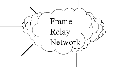
Topology is the map, or visual layout of the frame relay network. Frame relay network topology must be viewed from several perspectives to fully understand the network and the equipment used to construct the network. Topological views include an overview map, a logical connection map, perhaps a functional map, a map showing the detail equipment and channel links, an address map.
The map below is an overview where the frame relay switching is in the cloud in the center. The lines going out from the cloud represent the connections from the frame relay provider (phone company) to the customer premises. These are typically lines ranging in speed from 56000 bps to T-1 (1.544 Mbps) and faster. One or more DLCI numbers is assigned to each line end point. DLCI is discussed in more detail below. Over 900 DLCI's can be assigned, but frame relay networks rarely have that many, because a user does not need that many in most cases. There may also be limits due to constraints in the frame relay switching equipment. Also, a single network that is too large will be difficult to maintain.
The frame relay network shown above as a cloud can also be shown as a connection of end points tied to a central site, or a number of end points that are all meshed together.
End points tied to a central site is the traditional host to terminal model. The map below has 6 end points, just as in the previous map. Below, the end points are given meaning by defining one end as the host, the other 5 as the remotes. DLCI addressing could be assigned as follows:
Location	           DLCI #

Host end             16,17,18,19,20
Remote 1             16
Remote 2             16
Remote 3             16
Remote 4             16
Remote 5             16
At the frame relay switch, all remotes are mapped back to the host. At the host, Host 16 is mapped to Remote 1, Host 17 to Remote 2, Host 18 to Remote 3, Host 19 to Remote 4, and Host 20 to Remote 6. In practice, data from the host for Remote 5 arrives at the frame relay switch, from the customer equipment, with the destination address of 20. The frame relay switch, using its internal lookup table, finds that the data is for Remote 5, a physical port on the frame relay switch, that has a local address of 16. In the frame relay switch, address 20 is replaced with address 16 and the data is then delivered to Remote 5.
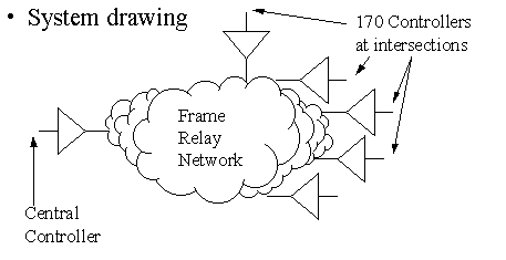
The frame relay network above is a typical installation. This drawing represents a system of traffic industry controllers known as "the model 170" (we know them as "intersection red lights" and a central control computer. It can also be shown as a traditional multidrop host to remotes, with lines bridged in the middle, as shown below:

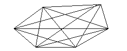
Frame relay also allows meshed networks. Since each endpoint can have one or more DLCI addresses, each user location can be connected to one other location, several locations, or all locations. If every location were connected to every other location, the network would be said to be "fully meshed". An illustration with all locations interconnected is below, next page.
Meshed network:
The fully meshed network mapping of DLCI's looks like this:
Location		DLCI #

Location 1           16,17,18,19,20
Location 2           16,17,18,19,20
Location 3           16,17,18,19,20
Location 4           16,17,18,19,20
Location 5           16,17,18,19,20
Location 6           16,17,18,19,20
This addressing can also be shown as a mapping table showing the addresses from the perspective of each one of the 6 locations. A frame relay switch requires this type of cross reference map. The switch uses the map to route the frame relay packets from one internal port of the switch to another port. The following table shows the local port number and the DLCI destination mapping that would be typical for a meshed network.
Local Port	DLCI Destination for the locations remote from the local port in
                                column 1


Location 1                16 = Port 2   17 = Port 3   18 = Port 4   19 = Port 5   20 = Port 6
Location 2                16 = Port 1   17 = Port 3   18 = Port 4   19 = Port 5   20 = Port 6
Location 3                16 = Port 1   17 = Port 2   18 = Port 4   19 = Port 5   20 = Port 6
Location 4                16 = Port 1   17 = Port 2   18 = Port 3   19 = Port 5   20 = Port 6
Location 5                16 = Port 1   17 = Port 2   18 = Port 3   19 = Port 4   20 = Port 6
Location 6                16 = Port 1   17 = Port 2   18 = Port 3   19 = Port 4   20 = Port 5
Frame Relay Assembler/Disassembler. A FRAD is a piece of networking equipment that assembles and disassembles data frames. For example, the DCB SR and SRX series of multiplexers assemble asynchronous data into frame relay frames. Hence, the SR is a FRAD for async data. Async data packaged by DCB multiplexers onto frame relay networks includes "dumb" terminal data. It includes PC data for remote control software of programs like PC Anywhere, Reachout, Carbon Copy and CoSession. DCB multiplexers are used to encapsulate in frame relay PPP protocol between host systems and PC's, between routers that use async PPP.
There are many examples of devices that encapsulate other protocols into frame relay protocol, and hence are know as FRADs. Frads are used to encapsulate ethernet MAC layer protocol, TCP/IP protocol, IPX protocol, IBM SDLC protocol, bisync protocol, Poll/Select polling protocols. Voice is being encoded for transmission over frame relay, especially voice that has been compressed via CELP, VSELP and similar methods.
Permanent Virtual Circuits. PVC's contrast with Switched Virtual Circuits (SVC). A connection to a network that allows connection and disconnection to various points is a switched virtual circuit. Circuits that are routed through software switching devices like X.25 pads and frame relay networks are virtual. A hard wired connected in a plain old circuit, not a virtual circuit.
Data Link Connections
Data Link Connection Identifier. This number identifies a virtual circuit. For a stat mux applications, a head end DCB SRX multiplexer might have 4 DLCI,s associated with it, while each of 4 remotes would have just a single DLCI. The following illustrates how DLCIs might be assigned in this example:
Host 	      Host 	  Remote	     Remote
Location      DLCI #      DLCI #           Location

Chicago        16            16            Milwaukee
Chicago        17            16            Minneapolis
Chicago        18            16            St. Louis
Chicago        19            16            Detroit
In the above example, the Chicago host location might be a single 56or 64 Kbps line into a DCB SRX-32 frame relay host mux. At each remote location there might be an SPL-08 multiplexer. The DLCI numbers are not necessarily assigned in any order by the carrier, although it is commonly done.
The above example illustrates that DCLI numbers have significance at the user's end point only. Chicago has 4 addresses, 16, 17, 18 and 19. At each remote, each location has the same number 16. The telephone company providing the frame relay service has a frame relay switch that translates the addresses. When these permanent virtual circuits are established, the relationship of the physical ports is mapped and then assigned DLCI numbers.
Vendor expectations and DCB frame relay multiplexers:
Vendors of frame relay services focus almost exclusively on LANs when explaining and selling frame relay. They also expect that a typical application with a single host site has a single line coming into the site, often at a high speed that is many times that of the remote locations. For example, the host may have a 256 Kbps router, and remotes (5, 10, 15 or more) at 56 Kbps each.
DCB frame relay multiplexers, such as the SRX-32, have a limited number of ports. Therefore, DCB may have the customer put in several 56 or 64 Kbps lines at the host, each serving a limited number of remote sites, typically between 2 and 8 (4 to 16 ports per remote site).
DLCI 0 (zero) and 1023 are reserved for management
DLCI 1 to 15 and 1008 to 1022 have been reserved for future use.
DLCI 992 to 1007 are reserved for layer 2 management of frame relay bearer service.
DLCI numbers 16 to 991 are available for subscribers for each user frame relay network
Protocols for exchanging information between a user FRAD and the frame relay network equipment. The protocols are:
LMI - The original interim management protocol, uses DLCI 1023. LMI was specified by the Frame Relay Forum.
Annex D - An ANSI T1.617 management protocol standard, uses DLCI 1. Annex D was specified by the ANSI T1.617 specification.
Annex A - Nearly identical to Annex D, used in Europe.
The is an inquiry from the frame relay user to the network every x seconds. The time value can be 5 to 30 seconds. The default value is 10 seconds for LMI and for Annex D. If the user does not make this inquiry every 10 seconds, the carrier network equipment will generate an alarm. The network equipment default value is 15 seconds. That is, the user should make an inquiry every 10 seconds, and the network expects the request every 15 seconds. The 5 second difference is a buffer time that allows for a small delay. The status inquiry returns status about the network. Sending the inquiry tells the network that the user FRAD is in service. When a status inquiry is not sent, the network will generate an alarm. An alarm may result in a "pro active" call to the customer from the service vendor. Status information is often collected by a FRAD and formatted into a MIB (management information base) for reporting via SNMP (simple network management protocol). Agents interface to the devices to collect the MIB's to deliver them to a manager.
This inquiry gets more information returned by network than is obtained in the Status Inquiry. Full status responses to the user from the network also returns all of the active DLCI numbers. The value can range from 1 to 255. The default value is 6, which means the user equipment sends 5 regular status inquiries, then the full status inquiry.
Indicates how frequently the FRAD should initiate a Status Inquiry Message. This is the 10 second timer referred to under the term "Status Inquiry".
Management Information Base, a piece of information collected for an SNMP manager.
A device that collects MIB's to report them to SNMP managers. HP's Open View is an example of a manager. The DCB product PA2000 is an agent, specifically a proxy agent that collects data from non-SNMP devices and reports the data to an SNMP manager like HP Open View, reporting the data in SNMP fomat.
Simple Network Management Protocol.
DCB is the leading manufacturer of "Async Framds", multiplexers for encapsulating async data over frame relay. The SR, SRX and Unimux series of multiplexers range in size from 4 to 32 ports. The multiplexers directly encapsulate async data without the need for external frads. A DCB frame relay multiplexer supports from 1 to 16 DLCI's, or locations, per host unit. With various digital sharing devices available from DCB, the frame relay multiplexers can be expanded to virtually any number of ports supported over a single frame relay link.
DCB frame relay multiplexers, since they directly encapsulate async data in frame relay protocol, eliminating the need for external frads, are very cost effective. DCB multiplexers can be directly cabled into your DSU, even a router (Cisco - see white paper on the DCB web site for more details).
DCB supplies other frame relay products to the market, including 56/64 Kbps DSU's, T1 and fractional T1 multiplexers, multi-protocol frads, frame relay routers. DCB sales and technical support personnel assist customers in evaluating the cost effectiveness of frame relay solutions. They also assist in selecting the optimum solutions among the many alternatives available.
Further, frame relay links can be very cost effective for delivering data from a central site to remote locations. Frame relay is very cost effective at distances of several hundred miles or more. In some areas of the U.S., frame relay is also very cost effective on a short distance basis. A short distance is the same LATA (local access and transport area). A LATA is the area served by your local phone company. As of this writing (Spring, 1997), frame relay is usually not cost effective on a local basis in the midwest (Wisconsin, Illinois, Michigan, Indiana, Ohio).
Consider frame relay for your network. It is no longer an experimental new service. Frame relay is tried and true, cost effective and reliable. Frame relay should be considered just one of many alternate ways of providing network services. Evaluate frame relay on an equal basis along side dial up, private line, DDS, T1, ISDN and similar services.
| Data Comm for
Business Inc. 2949 County Road 1000 E Dewey, Il 61840 |
Voice:
217-897-6600 Toll Free: 800-4-DCB-NET Toll Free: 800-432-2638 |
Email: Contact Page Web: www.dcbnet.com Fax: 217-897-8023 |
|
| All DCB web pages copyright ©1995- Data Comm for
Business, All rights reserved. EtherPath®, EtherSeries®, EtherPoll®, EtherBridge® and EtherModem® are Registered Trademarks of Data Comm for Business, Inc. |
|||